High Pressure Hydraulic Test Pumps
HP pumps for hydraulic testing of pressure equipment and systems
HII hydraulic test pumps help quickly and efficiently test various types of equipment in different modes.
Main types of tested equipment:
- Pressure vessels: cylinders, receivers, chemical reactors, tank trucks, tanks, pressure chambers, and boilers
- Tube-type, plate-type, and spiral-type heat exchangers
- Casings of pressure equipment: pumps, compressors, hydraulic cylinders, and drives
- Pipes and pipe assemblies, HP hoses and other types of hoses, flexible drill strings, and brake pipes
- Hydraulic, pneumatic, and gas supply lines
- Gas and oil pipeline sections, oil and gas equipment sections
- Stop valves, control valves, and pressure relief valves
- Valves of various types, including globe valves, gate valves, and ball valves
Main types of tests:
- Hydrostatic
- Cyclic
- Hydraulic fracturing, burst tests
- Leakage control
- Seat closure leak detection
- Adjustment of control and pressure relief valves
- Instrument calibration
For detailed description of HII pumps operation, application methods, and specific features of these pumps vs. electrically driven pumps for hydraulic testing, please refer to the "Pump Operation Procedure catalogue" (only Russian version available) located at "Download Catalogues" page.
Drive type: pneumatic
HII pumps of all series are pneumatically driven.
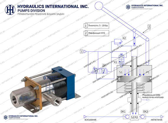
3L pumps (of the lowest flow rate) are equipped with a manual drive in addition to the pneumatic one. While operating 3L pumps, you do not have to switch over between the drives since both the pneumatic and manual drive are connected simultaneously. For 3L pumps functional diagram and operation description, please refer to the "Pump Operation Procedure" document.
HII pumps are not electrically driven, so such features as voltage class, electric power, and electric grid characteristics are not applicable to them.
For feeding the drives of HII pumps of all series, 5–10 bar oil-free industrial air is needed. The air shall contain no excessive moisture or mechanical impurities.
When pneumatically driven pumps are connected-up, no lubricator shall be installed in the air line since it is fatal for the drive.
The required air amount and the feeding compressor capacity depend firstly on the operation mode of a pump and varies from 0.1 to 10 m3/min.
For detailed information on the required air amount and quality, please consult our experts.
Hydraulic test pressures
Generally, the operation pressure range of the pumps is 0–4000+ bar. In this range, 99.9 % of hydraulic test objectives of engineering practice can be achieved. To achieve the rest 0.1 % of objectives, you can use HII one stroke intensifier, covering pressures up to 10,000 bar (150,000 PSI). This section does not cover one stroke intensifiers since they are used for very specific applications.
Each pump model has its own maximum operation pressure.
The minimum operation pressure for each pump model depends on specific features of its pneumatic drive. This value is especially important for hydraulic tests.
The minimum pressure of a pneumatic drive activation for a standard model is 1–2 bar. For a new pump, it is 1 bar, for a worn-out (but still operating) one, the minimum required pressure will grow up to 2 bar.
This minimum pressure value is the low limit of pressures at which a pump can run in “a pressure maintaining mode”.
"L" modification helps expand the pneumatic drive feed pressure range down to 0.2–0.3 bar and thus expand the operation pressure range limits.
In a constant flow operation mode, pumps of all series with no modifications will run faultlessly at any discharge pressures within pressure range starting from atmospheric.
Example. A pump builds up pressure from atospheric to 500 bar with an air drive pressure up to 5 bar (1:100). With air drive pressure below 1 bar, the pump will not start. It means that the pump will not be able to maintain test pressure below 100 bar. But when testing product at 500 bar, the pump will build up pressure gradually in the product from atmospheric to 500 bar without any limitations.
Flow range
Unlike all electrically driven positive displacement pumps that have a rated flow depending on a flow needed for a single shaft rotation and a shaft rotation speed, pneumatically driven pumps have no rated flow.
Furthermore, pneumatically driven pumps are not characterized with an operation flow range, unlike centrifugal pumps that have a flow range limited by 10 % of the rated flow value.
The pneumatic drive of the pump is operative within a speed range from 1 cycle per month to hundreds of cycles per minute.
There are some recommendations and methods for evaluating the service life of a pump in different operation modes.
It should be noted that any pneumatically driven equipment is designed for low speed and low flow applications.
Pneumatically driven pumps may be applied only within the following absolute limits:
- Discharge pressure of 0–86 bar: flow is 50 l/min max
- Discharge pressure of 86–700 bar: flow is 10 l/min max
- Discharge pressure of 700–1380 bar: flow is 5 l/min max
- Discharge pressure of 1380–4000+ bar: flow is 1–2 l/min max
These values are given for a single pump with a maximum capacity for this pressure class. For several pumps operating in parallel, the values will correspondingly increase.
The "Pump Operation Procedure" describes the methods of pump selection by flow in detail. However, the document covers only about 10 % of the information required for proper equipment selection.
Please consult our experts.
Pressure adjustment
HII pumps are designed as air driven hydraulic pressure amplifiers.
It means that they multiply the air drive pressure by an Area ratio defined as a ratio of the pneumatic drive piston area to the plunger area.
The Area ratio is the main specification for the pumps of this type.
To adjust a pump discharge pressure, it is necessary to set up appropriate air drive pressure with a pressure reducer or an I/P controller.
The discharge pressure adjustment accuracy will depend on the accuracy of air drive pressure setting. Ideally, it is possible to reach a very smooth and stepless discharge pressure adjustment. For pumps with a high Area ratio, the adjustment accuracy is lower.
Pneumatically driven pumps have a very high setting pressure repeatability. For most of the models, you should set up the discharge pressure only once, without any additional manual setting or continuous automated adjustment to reach high accuracy of discharge pressure repeating.
This property is of great importance for cyclic tests and hydraulic testing of large-scale manufactured products.
Exception: 3L spring-return pumps. These pumps are not applicable when the pressure repeatability is important.
The "Pump Operation Procedure" provides a detailed description of the discharge pressure adjustment with relevant trends and examples.
Flow adjustment
The pneumatic drive of HII pump allows adjusting the pump rod speed in a complete range, from zero to maximum values.
However, it should be noted that the pneumatic drive will not provide a highly accurate and constant flow required for high-accuracy dosing and performance testing. For such applications, positive displacement pumps with fixed rated flows shall be applied.
For most of the hydraulic test objectives, a pump flow adjustment is not an essential factor.
For valve seat closure leak detection, flow meters are used. A pump should maintain the required valve pressure or differential pressure and “automatically” compensate leakages without any automation equipment. Pneumatically driven pumps are perfectly suitable for this application.
The "Pump Operation Procedure" provides a detailed description of the flow adjustment with relevant trends and examples.
Pneumatic drive of HII pump allows keeping a tested product under pressure for a long time without actual liquid flow. This prevents:
- Liquid heating during hydraulic test
- Liquid contamination with wear debris
- Air ingress
- Power loss
- High frequency flow fluctuation.
Due to the pneumatic drive and plunger-type design, HII pumps:
- Do not contaminate the handled liquid, so they are a perfect solution for hydraulic testing where high purity liquids are required
- Require no bypass valve or pressure-relief valve for pressure adjustment
- Require no VFD and provide “automated” control without any automation devices
- Provide an extremely smooth, fast, and easy flow and test pressure control in a wide range: from zero to max values
- Require no electric power supply
Furthermore, they are:
- Perfectly suitable for pressure adjustment applications: in some operation modes, these pumps are much more efficient than electrically driven equivalents
- Designed for unlimited number of start and shutdown cycles and are perfectly suitable for applications with high cyclic loads
- Resistant to water hammer effects caused by hydraulic fracture of the tested product
- Fire- and explosion-proof
- Continious dry run resistant having low NPSHr and high self-suction capabilities.
- Lightweight and compact
- Not applicable for handling contaminated liquids and liquids with mechanical impurities
- Restricted usage for high flow applications
- Much more expensive than the electrically driven equivalent solutions for such applications as flushing and pressure testing of equipment with a capacity of over 100 m3, as well as for pre-filling of large capacity equipment and systems, where high continuous flows are required
- Not fit for gas phase pumping
- Not fit for high accuracy dosing
- Pure water, industrial water, oily water, water containing corrosion inhibitors
- Distilled water, deionized water
- Industrial oils, hydraulic oils, aircraft oils, mineral oils, synthetic oils, motor oils, loom oils
- Break fluids, skydrol
- Hydrocarbons, solvents
- Antifreeze compounds, ethylene glycol, non-freezing liquids
- High-purity liquids
- Explosion and fire hazardous liquids
- Chemically active and aggressive liquids


